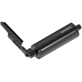
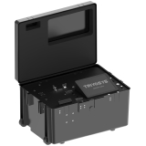
The TS-MPT-HS Series Pan & Tilt Unit is designed to perform precision positioning applications of various sensor units. It is designed for payloads up to 45 Kg. TS-MPT-MPT-HS pan & tilt units, designed according to military
standards and having compact structure, are resistant to all kinds of harsh conditions.
MPT-HS Series
The TS-MPT-HS Series Pan & Tilt Unit is designed to perform precision positioning applications of various sensor units. It is designed for payloads up to 45 Kg. TS-MPT-HS pan & tilt units, designed according to military standards and having compact structure, are resistant to all kinds of harsh conditions.
FEATURES AND ADVANTAGES
- Robust and compact design.
- High torque and performance.
- Precise positioning.
- High duty cycles.
- Suitable for fixed and mobile environments.
- 100% CNC Machined from high strength 6000 series aluminum and stainless steel.
APPLICATIONS
- Surveillance and Security: Motorized pan-tilt systems are often used in security cameras to monitor large areas. They can be programmed to scan a wide area or follow a moving target. Motorized pan-tilt systems can also be integrated with other security systems, such as facial recognition software, to enhance security measures.
- Robotics: Motorized pan-tilt systems are used in robotics to control the movement of robotic arms, cameras, and other devices. They can be used to manipulate objects, perform inspections, and conduct research. Motorized pan-tilt systems are also used in unmanned aerial vehicles (UAVs) to control the movement of cameras and sensors.
- Industrial Automation: Motorized pan-tilt systems are used in industrial automation to control the movement of robotic arms, conveyor belts, and other equipment. They can be programmed to move in a precise and repeatable manner, improving the efficiency and accuracy of manufacturing processes.
TS-MPT-HS
| Product Code | TS-MPT-HS-1 | TS-MPT-HS-2 | TS-MPT-HS-3 |
| Payload Capacity | 45 kg | 30 kg | 30 kg |
| Rated Torque at Tilt Axis | 70 Nm | 50 Nm | 50 Nm |
| Power Consumption | |||
| Max. Power Consumption | 100 W | 140 W | 140 W |
| Standby Power Consumption | 15 W | 20 W | 20 W |
| Heater Power | 40 W | 60 W | 60 W |
| Operating Voltage Range * | 18-32 V | 44-52 V | 44-52 V |
| Pan | |||
| Range of travel * | n × 360° (Continuous Rotation) | n × 360° (Continuous Rotation) | n × 360° (Continuous Rotation) |
| Max. Speed | 180 °/s | 180°/s | 180°/s |
| Min. Speed | 0.005°/s | 0.005°/s | 0.005°/s |
| Tilt | |||
| Range of travel * | 180° (+90°/-90°) | 180° (+90°/-90°) | 180° (+90°/-90°) |
| Max. Speed | 18 °/s | 60°/s | 60°/s |
| Min. Speed | 0.005°/s | 0.005°/s | 0.005°/s |
| Position Accuracy and Repeatability | |||
| Position Accuracy | 0.02° | 0.02° | 0.02° |
| Position Repeatability | 0.02° | 0.02° | 0.02° |
| Backlash | None at Tilt Axis | None at Tilt Axis 0.1° Pan Axis | None |
| Rotation Limits | |||
| Software Limits | Available | Available | Available |
| Mechanical Limits | Available at Tilt Axis | Available at Tilt Axis | Available at Tilt Axis |
| Encoder Type and Position Feedback | |||
| Encoder Type * | Absolute Encoder | Absolute Encoder | Absolute Encoder |
| Position Feedback | 0.005° | 0.005° | 0.005° |
| Operating Temperature | |||
| Working Temperature | -32°C to +55°C | -32°C to +55°C | -32°C to +55°C |
| Storage Temperature | -40°C to +60°C | -40°C to +60°C | -40°C to +60°C |
| Drive Systems | |||
| Drive System (Pan) | BLDC Motor | BLDC Motor | BLDC Motor |
| Drive System (Tilt) | Stepper Motor | BLDC Motor | BLDC Motor |
| Brake | Magnetic Brake | Magnetic Brake | Magnetic Brake |
| Construction | |||
| Exterior Finish | Powder Coat Black (Default), Special Finishes Available | ||
| Weight *** | 7 kg | 9 kg | 8.5 kg |
| Dimensions *** | 315.5x258.5x139 mm | 323.5x258.5x148.5 mm | 313.5x264.2x150.5 mm |
| Payload Mounting Type | Top and Side Mount | ||
| Ambient Conditions and EMI/EMC Compatibility | |||
| Electromagnetic Compatibility | MIL-STD-461G (CE102, CS101, CS114, CS115, CS116, CS118, RE102 and RS103) | ||
| Min. Operating and Storage Temperature | MIL-STD-810G, Method 502.6 Procedure II and Procedure I | ||
| Max Operating and Storage Temperature | MIL-STD-810G, Method 501.6 Procedure II and Procedure I | ||
| Thermal Shock | MIL-STD 810G, Method 503.6 Procedure I-C | ||
| Moisture Resistance | MIL-STD 810G, Method 507.6 Procedure II | ||
| Rain Resistance | MIL-STD-810G, Method 506.6 Procedure I | ||
| Dust and Sand Resistance | MIL-STD-810G, Method 510.6 Procedure I and Procedure II | ||
| Vibration Compatibility | MIL-STD-810G,Method 514.7 Procedure I | ||
| Shock Compatibility | MIL-STD-810G, Method 516.6 Procedure IV | ||
| Icing and Freezing Rain Resistance | MIL-STD-810G, Method 521.3 Procedure I | ||
| Protection / IP rating | IP67 | ||
| Control of Positioner Unit | |||
| Command and Control | GUI-Joysitck-Software | ||
| Protocol | TS-MPT Protocol and Pelco-D | ||
| Power Outputs to Payload * | |||
| 24 VDC - 2.4A | Optional | ||
| 12 VDC - 2.4A | Optional | ||
| 5 VDC - 2.4A | Optional | ||
| Instantly Monitoring | |||
| Power On and Run Time Monitoring | Available | ||
| Voltage Monitoring | Available | ||
| Current Monitoring | Available | ||
| Communication Interfaces to Payload ** | |||
| Serial | RS232, RS422, RS485 (2 Channel Configurable) | ||
| TTL | 1 Channel | ||
| IP | 1 Channel Gigabit Ethernet | ||
| Communication Interfaces to Pantilt | |||
| Serial | RS232 or RS422/RS485 | ||
| IP | Optional | ||
| Connectors * | |||
| Main Connector | D38999/20WD35PN | D38999/20WD35PN | D38999/20WD35PN |
| Payload Connector | D38999/20WD35SN | D38999/20WD35SN x2 | D38999/20WD35SN x2 |
| * If you have other requirements or need further assistance, please reach out to us. ** Configuration is available for particular lines including RF, SDI, HD-SDI, Fiber, etc. *** The specified values apply to top mount setups. Please note: Accessories such as cables and power supplies are not included in the package. | |||
MPT-HS
MPT-HS
SKU: TS-MPT-MD-032
Categories: Motorized Pan & Tilt Units, Pan & Tilt Units


